15. Switching to VGA
Written By: noah
- Difficulty
- Very Hard
- Estimated Completion Time
- 30 minutes
- Steps
- 2
Step 1 Wiring R, G, B and the Sync Lines
Using the twisted 34 AWG magnet wire we used to wire the USB lines, we will be wiring VGA to the LCD driver board.
- Twist and cut 4 lengths of magnet wire.
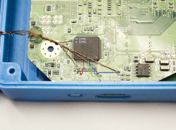
- Solder one wire to the R, G, and B channels as shown and the other to GND. Use a multimeter to verify GND points around the Wii motherboard if you're unsure of where to solder.
- Solder the remaining wire to the H/V sync pins on the video encoder as highlighted in the image. Ensure that the pins do not bridge.
- Run a wire from the mode via as shown, or the test point TP47 on the right-hand side of the video encoder, to 3.3V. Use a multimeter to verify 3.3V points around the Wii motherboard if you're unsure of where to solder.
- Solder the other end of each of the wire pairs to their corresponding pins on the driver board PCB. You can solder each of the GND wires to the single GND pin.
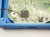
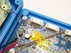
- Use tape or a small blob of hot glue as shown in the image to route the wires. There is an inductor on the LCD driver board that can cause interference if the wires get too close.
Step 2 Testing VGA


In order to test and verify that your wiring works, you'll need to grab the menu button PCB included with the display that we set aside earlier.
- Plug it into the middle connector on the driver board.
- When the G-Boy is powered on (hold the power button down for two seconds), press the "source" button to switch from composite video to VGA.
- If it pops up, go ahead and press the "Menu" button and once the OSD settings menu opens, use the menu button to navigate down to "Auto" and press the Up/Down button to auto adjust the image.

- If some of the white colors on your screen appear purple, go into the screen settings and turn the green channel down.