6. U10 Relocation
Written By: noah
- Difficulty
- Moderate
- Estimated Completion Time
- 5 minutes
- Steps
- 4
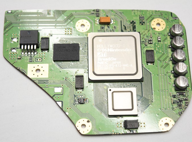
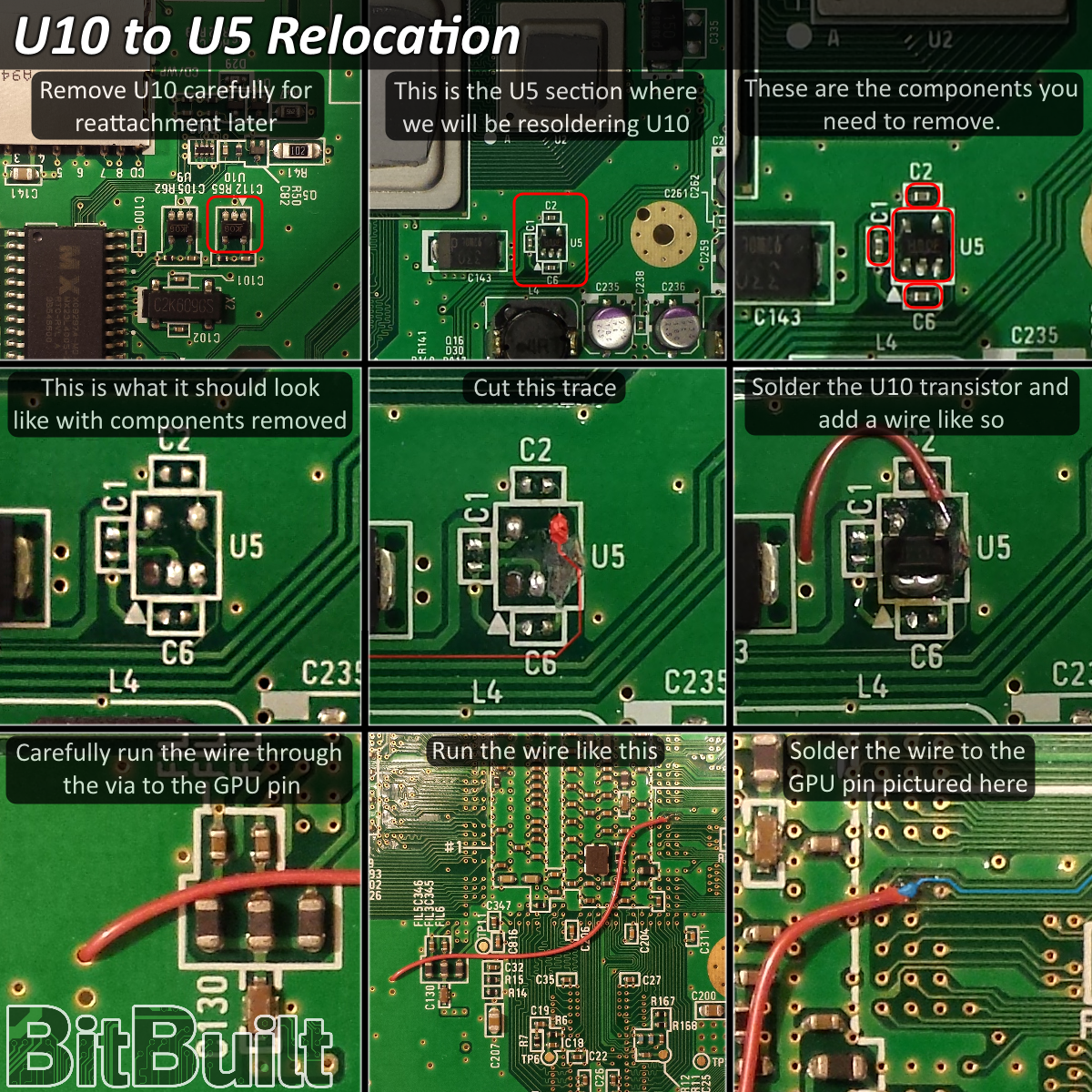
Step 1 Removing the U5
Before we can relocate the U10 IC, we must first remove the U5 in order to free up the space needed.
The following video shows the best method to remove the U10 and U5 ICs without a hot air station.
Use this method to desolder the U10 IC next to the MX chip as demonstrated in the video. Then, repeat the process to remove the U5 IC found next to the CPU and GPU.
Step 2 Soldering the U10
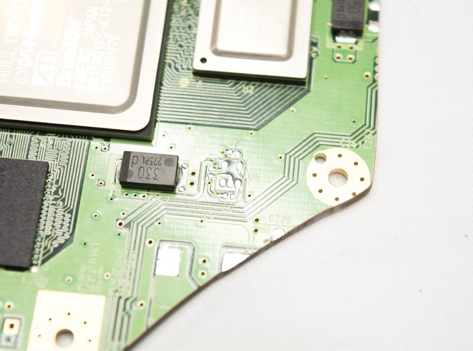

Before we solder the U10 to the board, we must first clean the solder off.
- Remove the resistors and capacitors around where the U5 was.
- Use flux and solder wick to clean up the solder left behind after removing the U5.
- Scrub this area with a toothbrush and some IPA to clean any flux residue.
- Place the U10 down and solder each of the legs.
- Be sure to bridge the front 3 legs together.
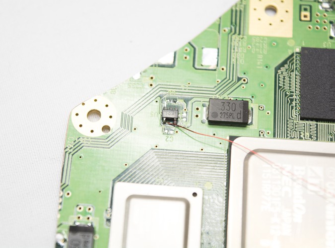
Step 3 Rewiring the U10
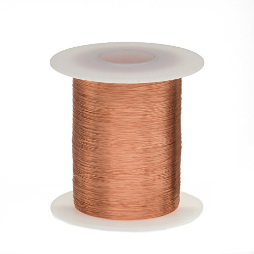 Remington Industries 34 AWG Magnet Wire, Enameled Copper Wire
- Solder a wire to the U10 to the leg as shown.
- Run the wire through the via shown in the image.
- Solder the other end of the wire into the via on the back of the motherboard as shown.
A detailed graphic on the U10 relocation, including the via to solder to, can be found here.
Step 4 Trim Complete
If you don't need to remove the LDO then great job - your trim is complete!
You can use a multimeter to ensure there are no shorts on any of the main voltage lines seen in the definitive Wii trimming guide found on the fourms here!
If you're building a G-Boy or plan on using a RVL-PMS from the BitBuilt Store (link here - don't delay, buy today!) then the LDO must be removed. Proceed to the next step.
If not, or if you've removed the LDO, wire up some regulators and video to test your work!

- If you wire everything up and the video is "slow" that means the U10 isn't functioning or connected properly.
