14. Wiring the Controller
Written By: noah
- Difficulty
- Hard
- Estimated Completion Time
- 15 minutes
- Steps
- 2
Step 1 Wiring the GC+ PCB
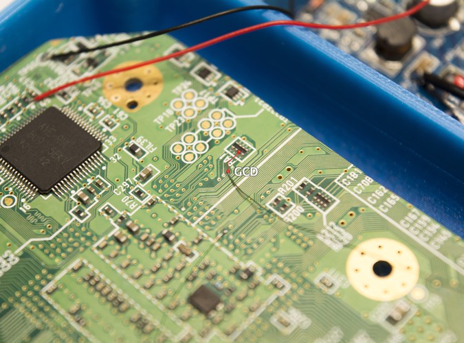

In order to get the controller working on the G-Boy, we need to run a data wire between the controller PCB and the Wii motherboard along with a voltage and ground wire in order to provide power to the controller board.
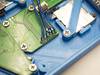
- Solder one end of magnet wire to the via as shown.
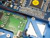
- Solder a wire to the second round 3.3V pad on the PMS, as well as one to a ground pad as shown.
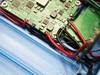
- Route the wires down along the LCD power wires and controller PCB power wires.
- Trim and tin the magnet wire and solder it to the "GCD" pad on the controller PCB. Solder the 3.3V wire to the pad labeled "3V3" and the ground wire to the "GND" pad.
Step 2 Wiring the Shoulder Button PCB
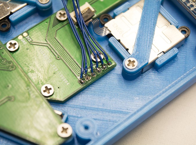
In order to get the L, R & Z buttons working we'll need to connect the shoulder button PCB we inserted in the back housing earlier to the controller PCB by soldering wires between them.
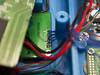
- First tin each of the pads on both PCBs. You may need to move the Wii motherboard out of the way as shown in order to reach the shoulder button PCB with your soldering iron.
- Using 30 AWG wire, solder a wire between each pad to the corresponding one on the other PCB.
- Ensure you use IPA with a toothbrush to clean where you've soldered. As seen in the image, tinning the pads leads to a lot of excess flux remaining on the board.
Once you've wired everything, put a cell into your G-Boy and test the buttons using the included GC+ 2.0 Configurator homebrew by selecting "Buttons test".