12. Wiring the RGB LED PCB & LCD Power
Written By: noah
- Difficulty
- Moderate
- Estimated Completion Time
- 15 minutes
- Steps
- 4
Step 1 Modifying the LCD Driver Board for 5V
The LCD driver board that comes with the G-Boy kit needs to be modified to run off of 5V by removing a single component, an inductor. If you own a hot air station, you can easily remove it by using that tool. Otherwise, watch this short video on removing the inductor using only a soldering iron:
If you already removed the inductor as instructed in section 8, you can skip this step.
Step 2 Wiring 5V
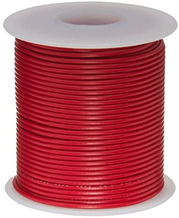 Remington Industries 22 AWG Gauge Stranded Hook-Up Wire
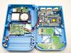
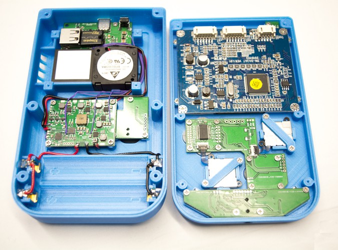
As mentioned earlier in the guide, we will be using the 5V pad on the RVL PMS to power the LCD driver board.
- Using the same type of 22 AWG wire you used for the battery clips, cut two wires; one for 5V and one for GND (Ground).
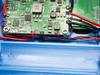
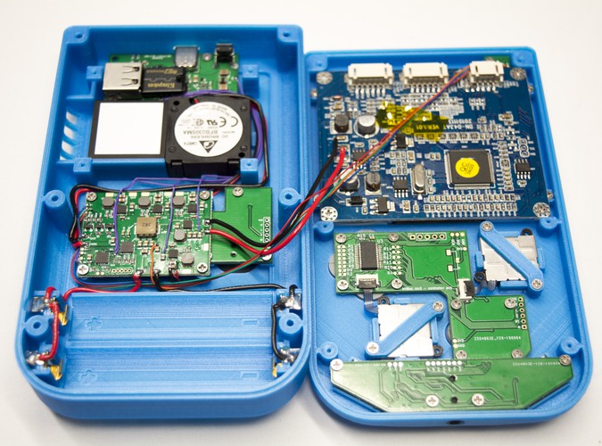
- Solder one end to the RVL-PMS as shown in the image.
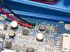
- Next, route the wires as shown in the images. Once you run it to where we removed the indcutor, trim the 5V wire, then strip it and tin it.
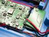
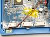
- Next, tin the top pad of the inductor footprint and solder the 5V wire to this pad.
- For the GND wire we will be soldering it to the capacitor (C147) right above the 5V pad as shown in the fourth image. You might need to add some solder to the capacitor in order to solder the wire.
- Once both your 5V and GND wires are secure on the LCD's driver board, you can move on to the next step.
Step 3 Wiring the RGB LED PCB
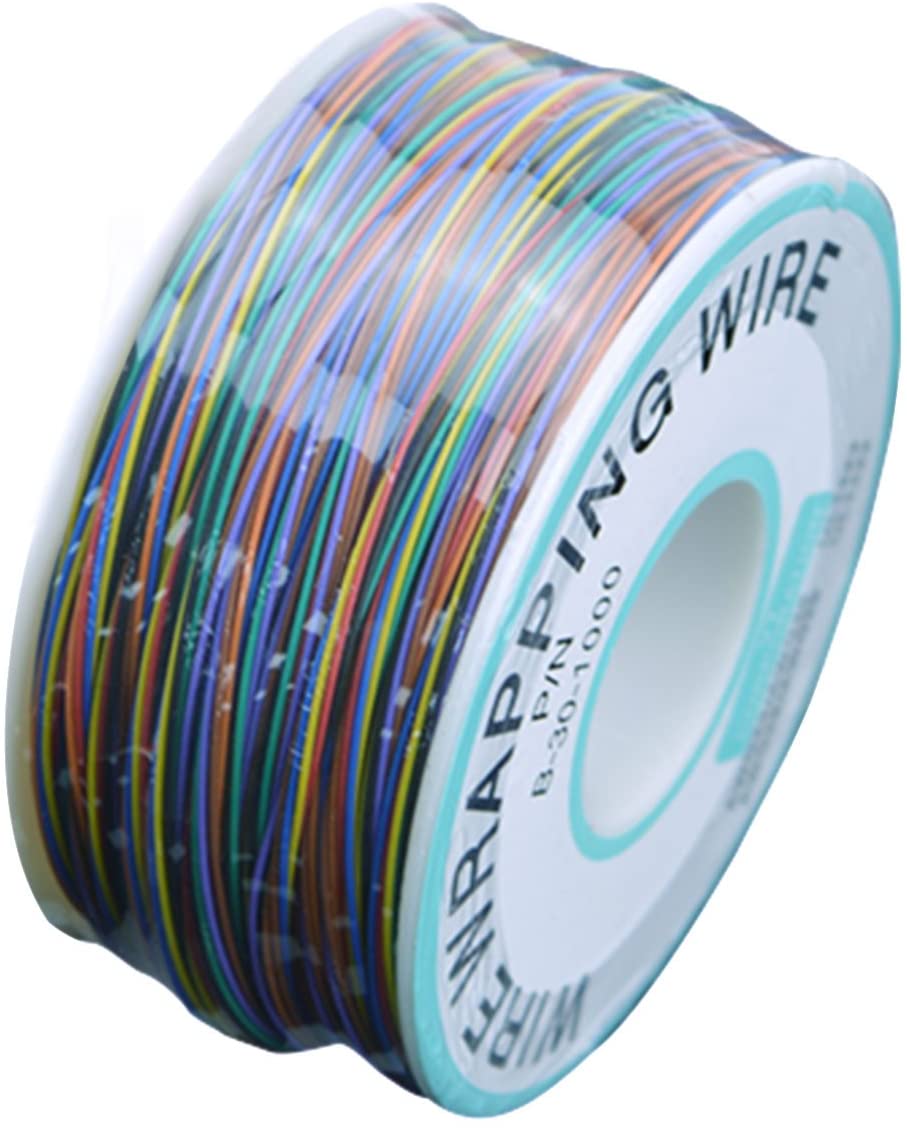 PVC Coated Tin Plated Copper Wire Wire-Wrapping 30AWG

Grab the same type of 30 AWG wire that you used earlier on the USB-C PCB wiring for this step.
- Tin the R, G, B, and VSYS pads on the PMS PCB and all 4 of the pads on the RGB LED PCB.
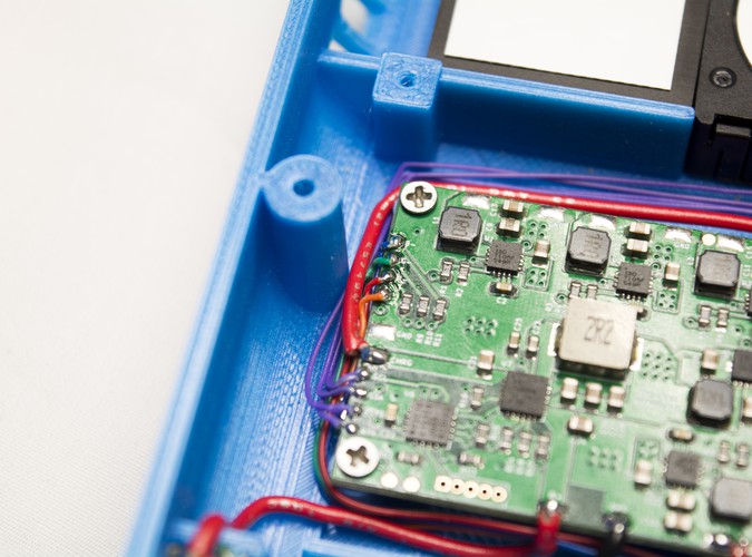
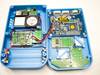
- Next, solder a wire to each of the R, G, B, and VSYS pads. As shown in the provided images, the color of the wire corresponds with each pad; red(R), green(G), and blue(B). VSYS is the orange wire.
- Route these wires underneath of the wires going to the battery clips as shown.
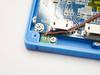
- Solder each wire to their respective pads on the RGB LED PCB.
- Once you're done, secure the stretch of wire to the driver board with a small piece of tape. In this instance, we've used kapton tape as it's thin, clear, and non-conductive.
Step 4 Testing and Verification
Before we move on to another section, it's important to first make sure that your wiring is correct and working.
- So, begin by placing one of your 18650 cells into the G-Boy. Like last time, always double check with a multimeter beforehand to make sure you connect it properly.
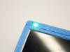
- Hold down the power button for a couple of seconds to turn the unit on as we previously did.
If your wiring is good then the RGB LED should turn on! Double tap the power button and it should switch modes. Here is a quick rundown of the three different modes:
- RGB Fade: This mode fades the LED through many different colors.
- Battery Status: This mode displays a color that corresponds with the current charge status of your G-Boy.
- Green - Fully Charged
- Yellow - ~50%
- Red - <20% remaining
- Shipping Mode: This mode will permanently turn off your G-Boy until a charger is plugged in. This is to prevent the unit from coming on if the button is accidentally pressed while it's enclosed.
If your LED turns on and is working, you can power your G-Boy off and remove the 18650 cell. Use this opportunity to clean off all the PCBs you just soldered with a toothbrush and IPA. Once everything is clean, this section is complete!