7. Wiring the USB-C PCB
Written By: noah
- Difficulty
- Moderate
- Estimated Completion Time
- 30 minutes
- Steps
- 4
Step 1 Wiring the Power Button
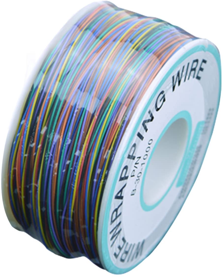 PVC Coated Tin Plated Copper Wire Wire-Wrapping 30AWG
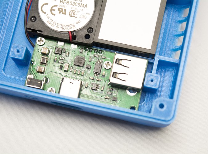
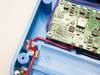
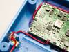
- Tin all the pads on the USB-C PCB as we will be soldering to all of them in this section of the guide.
- Once you're done, grab some thin wire and solder one end of it to the BTN pad on the USB-C PCB.
- Then, route it the same way we previously routed the fan power and ground wires. However this time ensure that the wire comes out along the left-hand side of the PMS, right next to the corresponding BTN pad on the PMS PCB.
- When you're done routing, trim any excess wire off and solder the other end of the wire to the BTN pad on the PMS.
Step 2 Wiring the I²C Lines & Voltage Lines
In order to communicate with the PMS to configure the USB Power Delivery, or PD which we'll refer to it as, and charge the G-Boy, the USB-C PCB must have the I²C pads wired to the PMS. Namely, these pads are SDA and SCL. We'll also need to run 5V and VSYS to the USB-C PCB so that the G-Boy can supply voltage the USB drive even when powered down.
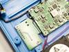
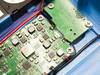
- Using more 30 AWG wire, attach a wire to both the SDA and SCL pads as well as the 5V and VSYS pads..
- Route them the same way we routed the BTN wire as well as the fan power wires.
- Once the wires are routed near the PMS, attach them as shown. Ensure that the wires are soldered to the correct pads as charging will not work with SDA/SCL inverted.
- TIP: Use two different colored wires to keep track of which line is which!
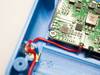
- Solder the 5V wire to one of the small round pads next to the bigger 5V pad as shown in the image.
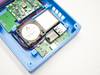
Step 3 Final Wiring and Testing

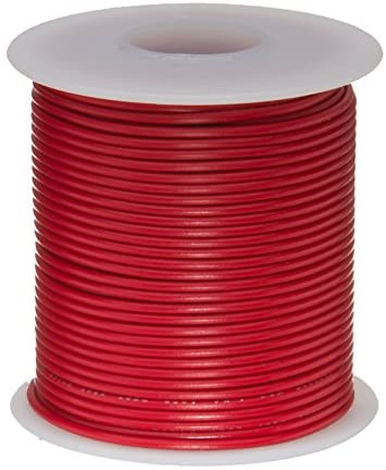 Remington Industries 22 AWG Gauge Stranded Hook-Up Wire
The last two wires we need to solder between the USB-C PCB and the PMS are the charging wire and a ground wire. For both of these lines, use the same type of wire you used for wiring up the battery clips to the PMS.
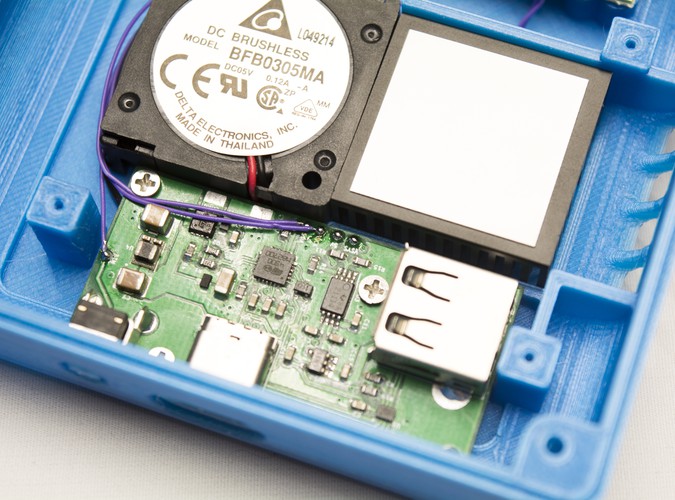
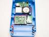
- Strip, tin, and solder the wires to the USB-C PCB as shown in the image.
- Route it around the square screw posts used for the Wii, and then around the USB-C wiring from the previous steps. If you have tweezers, you can pull the wire to form 90 degree bends in order to make the routing neater.
- Trim off any excess wire once you reach the CHRG and GND pads on the PMS PCB, then strip, tin, and solder the wires to the PMS.
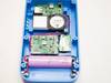
At this point, all the wiring between the USB-C PCB and the PMS is complete! Take a moment to clean up the spots you just soldered with a toothbrush and some Isopropyl alcohol (90%+).
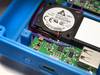
Once you've finished, take one of your 18650 cells and pop it into the slot in between the clips. Make sure to take note of the orientation you're inserting the cell at since you don't want to ruin all of your hard work by inserting it backwards! The positive end goes to the left (indicated by the + symbol in the case).
TIP: If you're unsure which end of the battery is positive, verify it with a multimeter first! This will also help you make sure the battery has a charge as well.
- When the cell is firmly seated in the case, press and hold the power button on the top of the G-Boy for about two seconds.
- This will turn the G-Boy on, and in turn allow us to make sure our wiring is working.
If the fan on the back of the G-Boy starts spinning then great job! This means that your PMS, power button, and fan are all wired correctly and working. You can now move onto the next step to check and see if your USB-C wiring works! Hold the power button again for around two seconds to power the G-Boy down. Make sure the fan stopped spinning before continuing.
If the fan doesn't come on, don't fret! Follow some of the troubleshooting tips below to try and diagnose the issue. You can use a multimeter to see if the PMS is outputting the correct voltage. In this case, 3.3V should be present on the power and ground wires going to the fan. For a quick video on how to use a multimeter to measure voltage, see this video.

- Use a multimeter to make sure the RVL-PMS turned on by probing any of the voltage pads to see if they're giving off the correct voltage.
- Use a multimeter to check to make sure that your ground wire is connected properly to the USB-C PD PCB. The power button requires ground in order to turn the G-Boy on.
- Measure the battery with a multimeter to ensure it's charged enough to power the RVL-PMS. If it's lower than 3.4-3.5V it will need to be charged before use.
Step 4 Testing the USB-C PCB
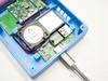
If the fan on the back of the G-Boy started spinning in the previous step, then your PMS powers on and should be outputting the correct voltages. This means that we can test and make sure the USB-C wiring is all working as intended.
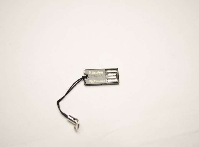
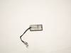
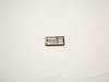
Grab the included microSD to USB adapter with your microSD card inside of it. Make sure to remove the small loop from the drive as shown in the images, as the metal end freely moving around inside of the case could cause potential shorts.
Once you've removed the loop, go ahead and plug the adapter into the USB port on the USB-C PCB. Grab a USB-C cable and plug your G-Boy into a computer. If everything is wired correctly, then the microSD adapter should open up on the computer you've plugged it into. As long as the contents of your microSD card are visible you're good to go!
To ensure PD charging is working, you can plug your G-Boy into a PD compliant charger and check the voltage on the CHRG pad on the PMS with a multimeter.