9. Mounting the Controls
Written By: noah
- Difficulty
- Easy
- Estimated Completion Time
- 25 minutes
- Steps
- 5
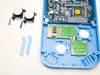
Step 1 Face Button Test Fit
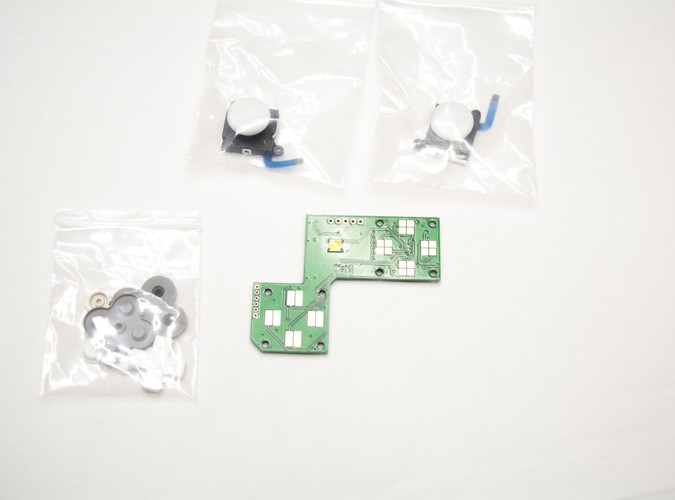

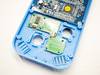

In this section, we will be mounting the last of the controller hardware to the front of the case. You can take the remaining items out of the parts bag labeled "Controller PCB". For this step you will only need your provided DS Lite buttons and membranes along with the start button from the bag labeled "3D Printed Parts". Also grab out 8 M2x4 screws from the bag labeled "Hardware".
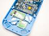
- Before we can insert the NDSL buttons, take notice that the membrane has to either be squished up against the case or cut off in order for it to sit flat against the buttons. For the sake of the guide we've cut the membrane and an image of it has been included.
- Scissors or a craft knife will work perfectly for removing the square of rubber.
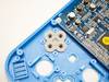
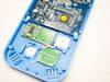
- Insert the A, B, X and Y buttons into their respective slots along with the D-pad and the start button.
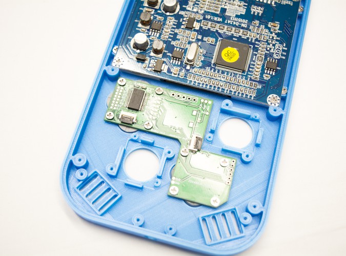
- Place the respective membranes over their buttons, and place the controller PCB over top.
- Use 2 of your M2x4 screws to secure the PCB from 2 screw posts diagonally opposite of each other as shown in the secondary image provided.
- Use this opportunity to test the feel of the buttons in the case. Make sure to hit the face buttons from multiple angles as well to ensure that they do not stick. If you are having any sort of issues such as a button sticking or a button being hard to press, proceed to Step 2. If everything lines up and feels great, you can skip to Step 3!
Step 2 Modifying the Button Retainers
As there are many different reproduction NDSL buttons available online, some of them come from different sources and may not fit exactly right inside of the G-Boy shell. The front casing can be modified very slightly to fix any sort of sticking button or hard to press issues you might encounter with NDSL buttons from different sources. A short video that will help you fix any and all issues you might have can be viewed on the left.
Step 3 Fully Securing the PCB
Once you are happy with the way your buttons feel, you can continue to screw in the rest of the M2x4 screws required to fully secure the controller PCB to the front half of the G-Boy.
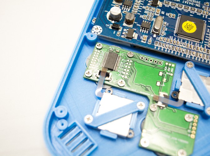
Step 4 Securing the Analog Sticks
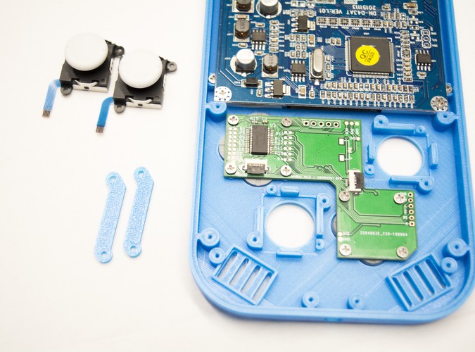
From the bag labeled "3D Printed Parts" grab out both of the analog stick mounts. Also from the bag labeled "Hardware" grab out 4 M2x4 screws.
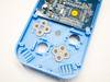
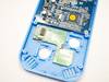
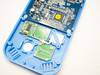
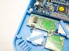
- Remove your analog sticks from the plastic bags they arrive in.
- Next, put one of them into the front casing as shown in the picture.
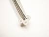
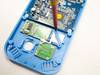
- Take one of the crossbar mounts and one of the M2x4 screws.
- Place the mount in the correct orientation and use the screw to fasten the mount to the casing.
- Once you're done, rotate the mount over top of the other screw post and secure it as well. Next, repeat the process for the remaining analog stick.
Step 5 Connecting the Analog Stick Cables
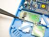
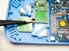
- Using a small pair of tweezers or another small hand tool like a plastic spudger, carefully open the FFC connectors on the controller PCB by pressing up on the black tab from underneath.
- Using tweezers, insert the cables connected to the analog sticks into the connectors.
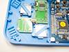
- Gently push the cables into the connectors until they don't go in any further. You do not want to damage the cables by being too rough!
- Close each black tab by pressing down on it until it clicks closed.
- Once both sticks are connected to the controller PCB, this section is complete!