6. Wiring the Power Hardware
Written By: noah
- Difficulty
- Moderate
- Estimated Completion Time
- 25 minutes
- Steps
- 4
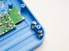
Step 1 Tinning the Battery Contacts
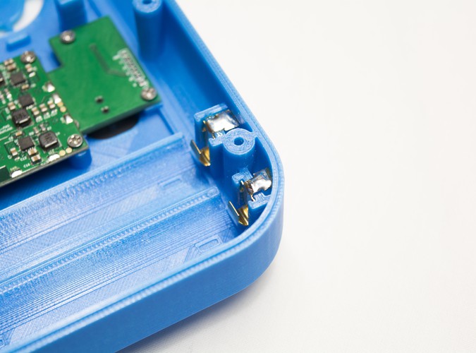
In this step, we'll be adding some solder to the battery clips using a process called tinning, outlined below. Using your soldering iron and solder, we'll need to tin the battery clips in order to get our power wire to stick to the metal.
- Hold your soldering iron on the clip you're tinning for a moment. CAUTION: Holding your soldering iron too long on these clips will melt your housing plastic!
- Feed the solder onto the clip. As long as your iron is hot enough, the solder should flow onto the clip and begin pooling on top.
- Once you've got enough solder (use the images for reference) on the clip you can move onto the next one.
- Repeat this process until all 4 clips are tinned.
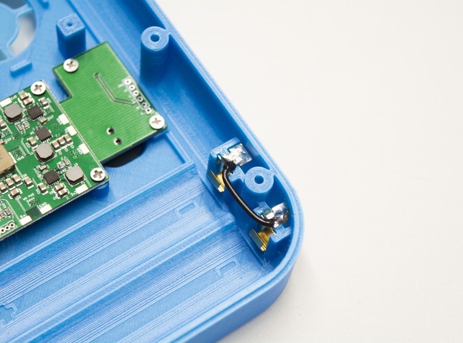
Step 2 Wiring the Clips Together
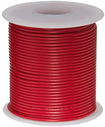 Remington Industries 22 AWG Gauge Stranded Hook-Up Wire
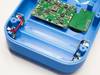
Since the RVL PMS requires our batteries to be in parallel configuration, we'll be wiring both our B+ and B- battery clips together before we wire them to the PMS.
For the G-Boy pictured, we used 22 AWG wire for wiring the battery clips together and to the PMS. The same wire should be used for your build.
- Start by cutting two small lengths of wire, one for each set of battery clips. Color is up to your preference, however in this example we've used red and black wires to signify B+ and GND (Ground) respectively.
- Strip and tin your wire and solder it to one of the clips.
- You can bend the wire to a 90 degree angle after attaching it to the clips as shown in the images to prevent excess from getting in the way.
Once you've connected both sets of clips to each other as shown in the second image, you are done with this step!
Step 3 Wiring the Clips to the PMS
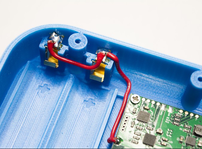
Using your soldering iron, tin the B+ and GND pads on the PMS as shown in the image.
- Cut another small section of 22 AWG wire and tin one end of it.
- Solder it to the top B+ battery clip, and then route the wire as shown in the image.
- Once it's near the B+ pad on the PMS, trim off any excess wire and strip the end.
- Tin the newly exposed wire and solder it to the B+ like in the provided image.
NOTE: As you can see in the image (around the B+/GND pads), there is flux on the PMS that comes from the solder used in the assembly (rosin core). It's important to clean the PCB using a toothbrush and at least 90% Isopropyl Alcohol. This will ensure that no corrosion takes place on any of the G-Boy circuit boards after assembly. Even though some flux may claim to be "no clean" it's still important to clean your PCBs.
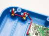
Repeat this process for the GND wire as well. Once you're done, your wires should look similar to the images provided.
It's important to ensure that your solder joints are solid. It's possible that if one of the wires is loose that it could come off once your G-Boy is fully assembled and short against something in the case. So take this time to ensure that everything looks good before proceeding. You should be able to lightly tug on all of your wiring without anything coming off to make sure that all of your joints are solid. Portions of the PMS PCB will be covered later by the trimmed Wii motherboard, so it's essential that everything is done correctly so that the Wii does not need to be removed from the housing for later maintenance.
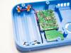
Step 4 Placing the Heatsink and Fan
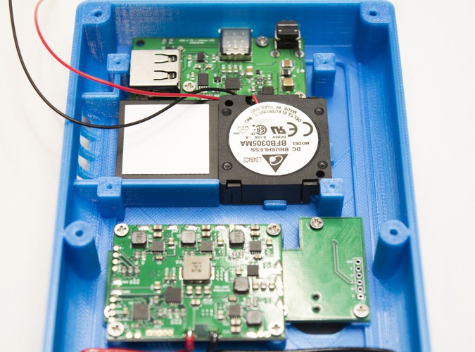
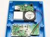
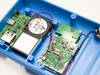
The fan is the next piece of hardware that needs to be wired to the PMS. It is held into place via friction and a couple of tabs on the back housing to keep it in place.
From the images included with this step, you can see that we've routed the power and ground cable for the fan around a few places. The entire process is listed here for your convenience:
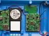
- Feed the wire underneath the mounted USB-C PCB. Ensure that it comes out between the screw post for the USB-C PCB and taller square screw post used for holding the Wii board in place.
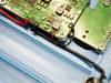
- Once the wires are routed through that spot, place the fan down. Make sure you pull the wires tight as slack can be pinched under the fan when placing it down! You'll notice towards the bottom of the fan next to the bottom right square screw post there's a gap where we'll be routing a few wires throughout the next few steps. Run your fan wires through this gap.
- Feed the wires underneath of the PMS but on top of the shoulder button PCB. This can be a bit tricky to do as the spacing is a bit tight, but as long as you're careful and don't bend the wires they should pass through on the bottom near where the batteries sit.
Once you've got both the power and ground wires poking out near the bottom of the PMS, you can pull them to size and cut any excess off. Strip the end of both wires off and tin each. Solder the red wire to either of the round pads next to the big 3.3V pad on the PMS. Make sure to tin whichever pad you're going to use before soldering the wire to it. The black wire can be soldered to any ground pad on the PMS.